The NoCAN event protocol over TCP/IP
This document describes the protocol that the nocand server uses to communicate
with clients like nocanc over TCP/IP.
By implementing this protocol, users can create alternative clients to
nocanc or language bindings for C, Python, etc. Note that this protocol should
not be confused with the CAN bus protocol used by nodes to communicate with
each other in a NoCAN network.
A client (e.g. nocanc) initiates a communication with the nocand server is
as follows:
- The client connects to server and sends a ClientHello event.
- The server responds with a ServerHello event, including version information.
- The client sends a ClientAuth event, containing a secret API key.
- The server sends a ServerAck event with a “OK” status, if the API key is correct.
- The client sends a Subscribe event, containing all event types it wants to receive.
- The server sends a ServerAck event confirming the subscription.
After this initialisation, the server will push subscribed events to the client. The client can send events to the sever as well at any time.
The NoCAN event manager typically listens for connections on TCP port 4242, though this is fully configurable by the user. The protocol described in this document should be usable without change to run over TLS/SSL, as an option available in the future.
Event packets
Events are encoded in packets with the following structure:
| EventId | Length | Value |
|---|---|---|
| 1 byte | 1-5 byte(s) | Length byte(s) |
EventId is a number that uniquely identifies the type of event.
Length describes the size of the following event value.
Value describes data associated to the event. The structure and size of
Value is event dependent. In general, Value elements are encoded with
the most significant byte first.
EventId
The event identifier EventId is represented as one byte. Currently, there are 20
different types of events:
const (
    NoEvent                          EventId = 0
    ClientHelloEvent                         = 1
    ClientAuthEvent                          = 2
    ClientSubscribeEvent                     = 3
    ServerAckEvent                           = 4
    ServerHelloEvent                         = 5
    BusPowerStatusUpdateEvent                = 6
    BusPowerEvent                            = 7
    ChannelUpdateRequestEvent                = 8
    ChannelUpdateEvent                       = 9
    ChannelListRequestEvent                  = 10
    ChannelListEvent                         = 11
    NodeUpdateRequestEvent                   = 12
    NodeUpdateEvent                          = 13
    NodeListRequestEvent                     = 14
    NodeListEvent                            = 15
    NodeFirmwareUploadEvent                  = 16
    NodeFirmwareDownloadRequestEvent         = 17
    NodeFirmwareDownloadEvent                = 18
    NodeFirmwareProgressEvent                = 19
    NodeRebootRequestEvent                   = 20
    BusPowerStatusUpdateRequestEvent         = 21
    DeviceInformationRequestEvent            = 22
    DeviceInformationEvent                   = 23
    SystemPropertiesRequestEvent             = 24
    SystemPropertiesEvent                    = 25
)
These events are detailed in the following section (“Events Semantics”).
Length
The encoding of length is almost similar to the one used in ASN.1 DER:
- If
length<=128thenlengthis encoded as one byte. - if
length>128andlength<256thenlengthis encoded as the character0x81followed by the value oflengthas one byte. - if
length>=256(i.e. 2^8) andlength<65536then thenlengthis encoded as the character0x82followed by the value oflengthas two byte, most significant byte first. - if
length>=65536(i.e. 2^16) andlength<16777216then thenlengthis encoded as the character0x83followed by the value oflengthas three byte, most significant byte first. - if
length>=16777216(i.e. 2^24) andlength<4294967296then thenlengthis encoded as the character0x84followed by the value oflengthas three byte, most significant byte first.
Examples:
- 15 is encoded as [ 0x0F ]
- 150 is encoded as [ 0x81 0x96 ]
- 1500 is encoded as [ 0x82 0x05 0xDC ]
Value
Values are encoded as a string of bytes. The encoding is event dependent and is described hereafter in the section titled “Event Specification”. As a general rule, multi-byte numbers (e.g. a 16 bit integer) contained within a structured value are represented with their most significant byte first.
Examples:
- As a 16 bit number, 258 is encoded as the string of bytes [ 0x01 0x02 ]
- As a 32 bit number, 258 is encoded as the string of bytes [ 0x00, 0x00, 0x01 0x02 ]
- As a 32 bit number, 3735928559 is encoded as [ 0xDE 0xAD, 0xBE, 0xEF ]
Server decoding error
When a server fails to decode an event it will respond with a ServerAckEvent with an Ack code set to 1 or 4, and will close the connection.
See below for further details about the ServerAckEvent.
Event Specification
This section describes how an event Value is encoded, depending on the specified EventId.
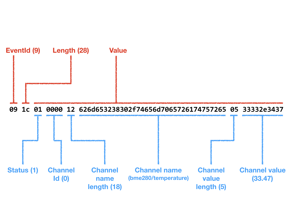
The following figure shows an example of a ChannelUpdate event message. The EventId is 9, the value length is 28 and the event value is further broken down into subfields according to the structure of a ChannelUpdate event value.
ClientHelloEvent (1)
This event is sent at the start of session by the client. It contains no value and has a null length.
The server should respond with a ServerHelloEvent.
ClientAuthEvent (2)
A client sends an ClientAuthEvent to authenticate to the server, by presenting an authentication token. If the authentication is successful the client will be authorised to send any type of event to the server. Unauthenticated clients can only send ClientAuthEvent and ClientHelloEvent messages.
The content of the ClientAuthEvent message is simply a string representing an authentication token:
| Authenticator |
|---|
| n byte(s) |
The server will respond to this message with a ServerAckEvent. If the authentication is successful, the server will set a response code to
- The client can then use the ClientSubscribeEvent message to select what data it wants to receive from the server.
ClientSubscribeEvent (3)
This message allows the client to specify what messages (events) it wants to receive from the server. While the client can send any type of event, the server will only send events that are specified through the ClientSubscribeEvent message (in addition to the ServerAckEvent which is always sent).
The ClientSubscribeEvent message value is formed as a list of EventId codes, describing the events the client subscribes to:
| Event Id 1 | Event Id 2 | … | Event Id N |
|---|---|---|---|
| 1 byte | 1 byte | … | 1 byte |
In response to this message, the server will send a ServerAckEvent message.
ServerAckEvent (4)
This message indicated the success or failure of the last operation requested by the client (e.g. authentication).
The value is a a one byte string:
| Ack code |
|---|
| 1 byte |
The meaning of the Ack code is as follows:
| Ack Code | Meaning |
|---|---|
| 0 | Success |
| 1 | Bad or Malformed Request |
| 2 | Unauthorised / missing authentication |
| 3 | Not found |
| 4 | General failure |
ServerHelloEvent (5)
This event is sent by the server to the client in response to a ClientHelloEvent. The value of this event is a fixed string of 4 bytes:
| Byte 1 | Byte 2 | Byte 3 | Byte 4 |
|---|---|---|---|
| 0x45 | 0x4D | 0x01 | 0x00 |
Byte 3 and byte 4 are used to indicate the major and minor version of then event manager server. Currently, this is 1.0 as shown above.
Once the client has received a ServerHelloEvent, it should proceed with a ClientAuthEvent.
BusPowerStatusUpdateEvent (6)
The server will periodically send a BusPowerStatusUpdateEvent message reflecting the power status of the NoCAN network.
The value of this event is structured as follows:
| Status | Voltage | Current sense | Reference Level |
|---|---|---|---|
| 1 byte | 4 bytes (float) | 2 bytes | 4 bytes (float) |
The value is encoded in big endian.
Status is an array of bits representing the state of the CAN bus driver.
| Bit | Name | Description |
|---|---|---|
| 0 | RX_PENDING | A CAN bus message is available in the driver. |
| 1 | TX_PENDING | The output transmission buffer of the driver is full. |
| 2 | N/A | |
| 3 | N/A | |
| 4 | ERROR | A network error occurred. |
| 5 | FAULT | An over-current event caused the driver to shut down power. |
| 6 | POWERED | The network is powered. |
| 7 | CAN_RES | The 120 ohm termination resistor is disabled on the PiMaster. |
Voltage is a 32 bit float representing the measured voltage on the network (e.g. 12V).
Current Sense is a 16 bit value representing a rough estimation of the current used by the network.
Reference Level is a 32 bit float representing the measured voltage on the PiMaster board MCU (typically 3.3V).
BusPowerEvent (7)
When the server sends a BusPowerEvent it means that the power on the NoCAN network has been switched on or off.
This message has a one byte value:
| Power |
|---|
| 1 byte (0x00 = off, 0x01 = on) |
When a client sends a BusPowerEvent to the server, it means that it requests the power to be switched on or off on the NoCAN network. The server will respond with a BusPowerEvent reflecting the state of the power on the network (it should be the same message as the client sent).
ChannelUpdateRequestEvent (8)
A client will send a ChannelUpdateRequestEvent to ask the server to report the status of a particular channel.
The message has the following structure:
| Channel Id | Channel name length | Channel name |
|---|---|---|
| 2 bytes | 1 bytes | 0 to 63 bytes |
The Channel Id represents a 16-bit channel identifier. The Channel Name is the textual name of the channel. The client can specify a channel either by id or by name. When the Channel Id is not 0xFFFF, this value is used to specify a channel. When the Channel Id is 0xFFFF, the name is used instead.
The server will respond to this request with a ChannelUpdateEvent.
ChannelUpdateEvent (9)
A server will send a ChannelUpdateEvent of any change occurs on a channel or if it receives a ChannelUpdateRequestEvent from a client. Notably, a ChannelUpdateEvent will be emitted each time data is published on a channel.
The message has the following structure:
| Status | Channel Id | Channel name length | Channel name | Channel value length | Channel Value |
|---|---|---|---|---|---|
| 1 byte | 2 bytes | 1 bytes | 0 to 63 bytes | 1 byte | 0 to 63 bytes |
The Status byte can have the following values:
| status | Description |
|---|---|
| 0 | A channel was created. |
| 1 | A channel was updated, data was published on the channel. |
| 2 | A channel was destroyed. |
| 3 | The requested channel does not exist (in response to a ChannelUpdateRequestEvent only). |
The fields Channel Id and Channel Name are the same as in the ChannelUpdateRequestEvent.
The field Channel value represents the current content of a channel. It is non-empty when status is 1 (channel updated); in all other cases, Channel value length is 0 and Channel value is empty.
ChannelListRequestEvent (10)
When the client sends this message, the server will respond with a ChannelListEvent containing a list of all active NoCAN channels.
This message has no value.
ChannelListEvent (11)
The server will sent a ChannelListEvent in response to a ChannelListRequestEvent sent by a client.
The message has the following structure:
| Channel Update event 1 | … | Channel Update event x |
|---|---|---|
| N[1] bytes | … | N[x] bytes |
Each block in this message has the structure defined in the ChannelUpdateEvent message described previously.
NodeUpdateRequestEvent (12)
The client can send a NodeUpdateRequestEvent to request the server to send information about the state of a particular node in a NoCAN network.
| Id |
|---|
| 1 byte |
Id is a number between 1 and 127 that identifies a node.
The server will send a NodeUpdateEvent in response to this message.
NodeUpdateEvent (13)
The server will send a NodeUpdateEvent when the state of a node changes or in response to a NodeUpdateRequestEvent.
The message has the following structure:
| Id | State | UDID | Last seen |
|---|---|---|---|
| 1 byte | 1 byte | 8 bytes | 8 bytes |
Id is a number between 1 and 127 uniquely identifying the node in the NoCAN network.
State described the current state of a node.
UDID is a 8 byte identifier of the node, globally unique across all NoCAN networks.
Last seen is a 64 bit number, encoded with the most significant byte first, which represents a UTC nanosecond timestamp indicating when the node was last seen (time starts on Jan 1st, year 1 at 00:00:00).
NodeListRequestEvent (14)
When the client sends this message, the server will respond with a NodelListEvent containing a list of all active NoCAN nodes.
This message has no value.
NodeListEvent (15)
The server will sent a NodeListEvent in response to a NodeListRequestEvent sent by a client.
The message has the following structure:
| Node Update event 1 | … | Node Update event x |
|---|---|---|
| N[1] bytes | … | N[x] bytes |
Each block in this message has the structure defined in the NodeUpdateEvent message described previously.
NodeFirmwareUploadEvent (16)
A client will send a NodeFirmwareUploadEvent to upload a new firmware to a node.
After the client sends this message, the server will send NodeFirmwareProgressEvent messages to the client until the firmware has been successfully uploaded.
The message has the following structure, which is common to the NodeFirmwareDownloadEvent message event as well as the NodeFirmwareDownloadRequestEvent:
| Node Id | Download | Limit | Firmware blocks |
|---|---|---|---|
| 1 byte | 1 byte | 4 bytes | N bytes |
Node Id identifies the node to be updated.
Download describes whether the event relates to firmware upload (0x00) or firmware download (0x01). This value is 0x00 for a NodeFirmwareUploadEvent and 0x01 for a NodeFirmwareDownloadEvent.
Limit is used for downloads and sets a limit on the maximum number of bytes to download. This value is ignored for a NodeFirmwareUploadEvent and can be safely set to 0 in that case.
Firmware blocks is an array of block of flash memory content that have the following structure.
| Offset | Length | Data |
|---|---|---|
| 4 bytes | 4 bytes | Length bytes |
Where:
- Offset describes the flash starting address.
- Length described the length of the flash data.
- Data is the actual data.
For a NodeFirmwareUploadEvent a firmware block describes data to be written to flash.
For a NodeFirmwareDownloadEvent a firmware block describes data that was read from flash.
For a NodeFirmwareDownloadRequestEvent the firmware block is empty.
There is usually only one firmware block in a NodeFirmwareUploadEvent or a NodeFirmwareDownloadEvent.
NodeFirmwareDownloadRequestEvent (17)
A client will send a NodeFirmwareDownloadRequestEvent to download firmware from a node.
The message has the same structure as a NodeFirmwareUploadEvent described above, with the following specifics:
- Limit sets the maximum flash download size, where a value of 0 means all the flash (248K).
- Firmware blocks is empty and has therefore a null length.
After the client sends this message, the server will send several NodeFirmwareProgressEvent messages to the client until the firmware has been successfully downloaded.
Once the firmware has been successfully downloaded, the server will send a NodeFirmwareDownloadEvent with the content of the downloaded firmware.
NodeFirmwareDownloadEvent (18)
A server will send this message to a client once a flash download is completed, after being initiated by a NodeFirmwareDownloadRequestEvent.
The message has the same structure as a NodeFirmwareUploadEvent described above, with the following specifics:
- Download has the value 0x01.
- Firmware blocks contains exactly one block, with the downloaded firmware.
NodeFirmwareProgressEvent (19)
During the upload or download of firmware, the server will send NodeFirmwareProgressEvent indicating the progress of the operation.
The message has the following structure:
| Node Id | Progress | Bytes transferred |
|---|---|---|
| 1 byte | 1 byte | 4 bytes |
Node Id identifies the node which is undergoing firmware upload or download.
Progress is an integer indicating the progress of the operation expressed as a percentage (0 to 100). The special value 0xFE indicates a success of the operation, while the special value 0xFF indicates a failure.
Bytes transferred describes the number of bytes of firmware that have been successfully uploaded or downloaded ignoring any additional overhead (message headers, ACK messages, etc.)
NodeRebootRequestEvent (20)
This message is sent by the client to request a particular node to reset the main MCU (SAMD21G18) through a hard reset.
The message has the following structure:
| Node Id |
|---|
| 1 byte |
Node Id identifies the node that must be rebooted.
In response to this message, the server will send a ServerAckEvent message, which will either indicate success (status 0x00) or that the node was not found (status 0x03).
BusPowerStatusUpdateRequestEvent (21)
When the client sends this message, the server will respond with a BusPowerStatusUpdateEvent.
DeviceInformationRequestEvent (22)
To be detailed
DeviceInformationEvent (23)
To be detailed
SystemPropertiesRequestEvent (24)
To be detailed
SystemPropertiesEvent (25)
To be detailed